Royal924
-
Postów
28 -
Dołączył
-
Ostatnia wizyta
Typ zawartości
Profile
Forum
Wydarzenia
Treść opublikowana przez Royal924
-
forumowy projekt opensource systemu pirotechnicznego
Royal924 odpowiedział(a) na zk1959 temat w Forumowy system pirotechniczny
I understand good luck, let your eyesight be better. screenshot looks great -
forumowy projekt opensource systemu pirotechnicznego
Royal924 odpowiedział(a) na zk1959 temat w Forumowy system pirotechniczny
Hello, Any news about making Pyrobox available? -
forumowy projekt opensource systemu pirotechnicznego
Royal924 odpowiedział(a) na zk1959 temat w Forumowy system pirotechniczny
great news. Please write who would like to participate in the development of ignition system, make a complete design of dps, sdma components, standard size in the briefcase. -
forumowy projekt opensource systemu pirotechnicznego
Royal924 odpowiedział(a) na zk1959 temat w Forumowy system pirotechniczny
glad to join you -
forumowy projekt opensource systemu pirotechnicznego
Royal924 odpowiedział(a) na zk1959 temat w Forumowy system pirotechniczny
that would be fantastic If I could ask, Avula, would that be possible? -
forumowy projekt opensource systemu pirotechnicznego
Royal924 odpowiedział(a) na zk1959 temat w Forumowy system pirotechniczny
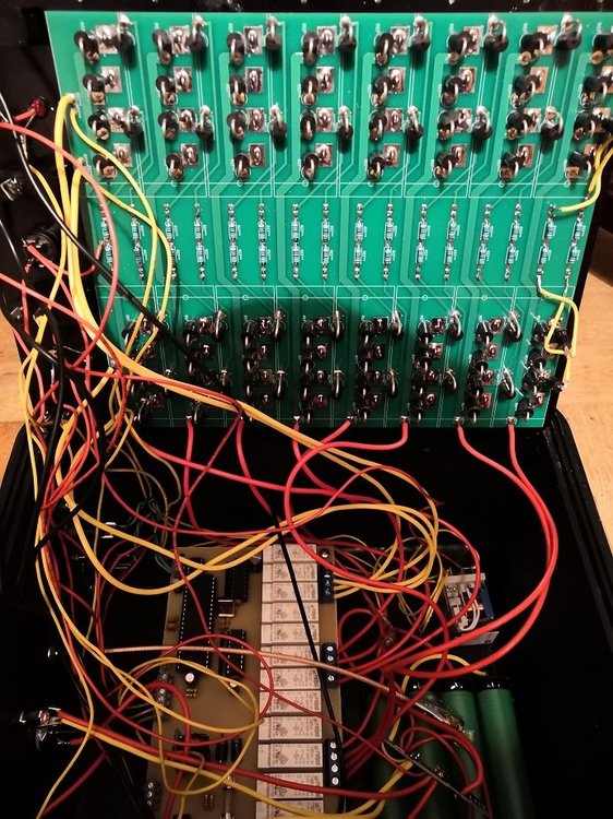
My new knk1302, terminals soldered directly to pcb. Sadness there is no further progresion, remode ling to mosfet and all on one pcb.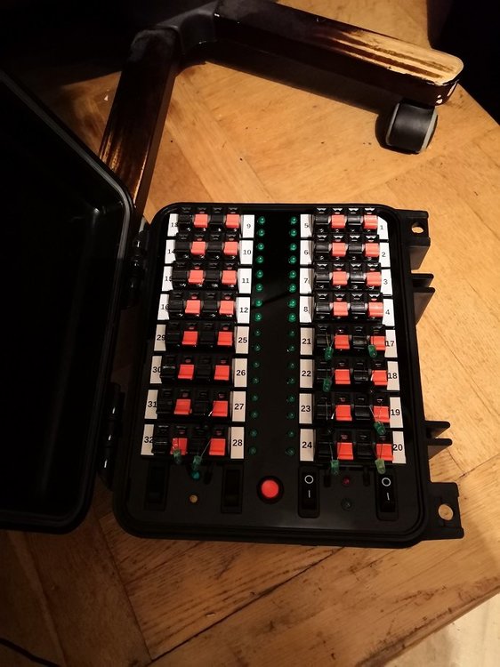


-
forumowy projekt opensource systemu pirotechnicznego
Royal924 odpowiedział(a) na zk1959 temat w Forumowy system pirotechniczny
Good idea -
forumowy projekt opensource systemu pirotechnicznego
Royal924 odpowiedział(a) na zk1959 temat w Forumowy system pirotechniczny
Hi, when I turn knk1302 off and I turn it on, it does not remember the module number set. Where can be a mistake? Thank you -
forumowy projekt opensource systemu pirotechnicznego
Royal924 odpowiedział(a) na zk1959 temat w Forumowy system pirotechniczny
Yes I know it only works with the knk1301;) That's not a problem for me. But addressing it is a bit unfortunate. -
forumowy projekt opensource systemu pirotechnicznego
Royal924 odpowiedział(a) na zk1959 temat w Forumowy system pirotechniczny
It's looking great. What happens if I have 3 modules set to number 1. Each module will have a different number of cues. -
forumowy projekt opensource systemu pirotechnicznego
Royal924 odpowiedział(a) na zk1959 temat w Forumowy system pirotechniczny
Pokud jste nastavil špatně lock bits, nejde to vrátit. Nelze odemknout. Atmega 16 je nepoužitelný. Časově nejúspornější je naprogramovat novou Atmega 16. If you have set wrong lock bits, you can not go back. Can not unlock. Atmega 16 is unusable. The most time consuming is to program the new Atmega 16 correctly -
forumowy projekt opensource systemu pirotechnicznego
Royal924 odpowiedział(a) na zk1959 temat w Forumowy system pirotechniczny
Yannic does not respond, for more than a month does not respond (I tried forum, email) -
forumowy projekt opensource systemu pirotechnicznego
Royal924 odpowiedział(a) na zk1959 temat w Forumowy system pirotechniczny
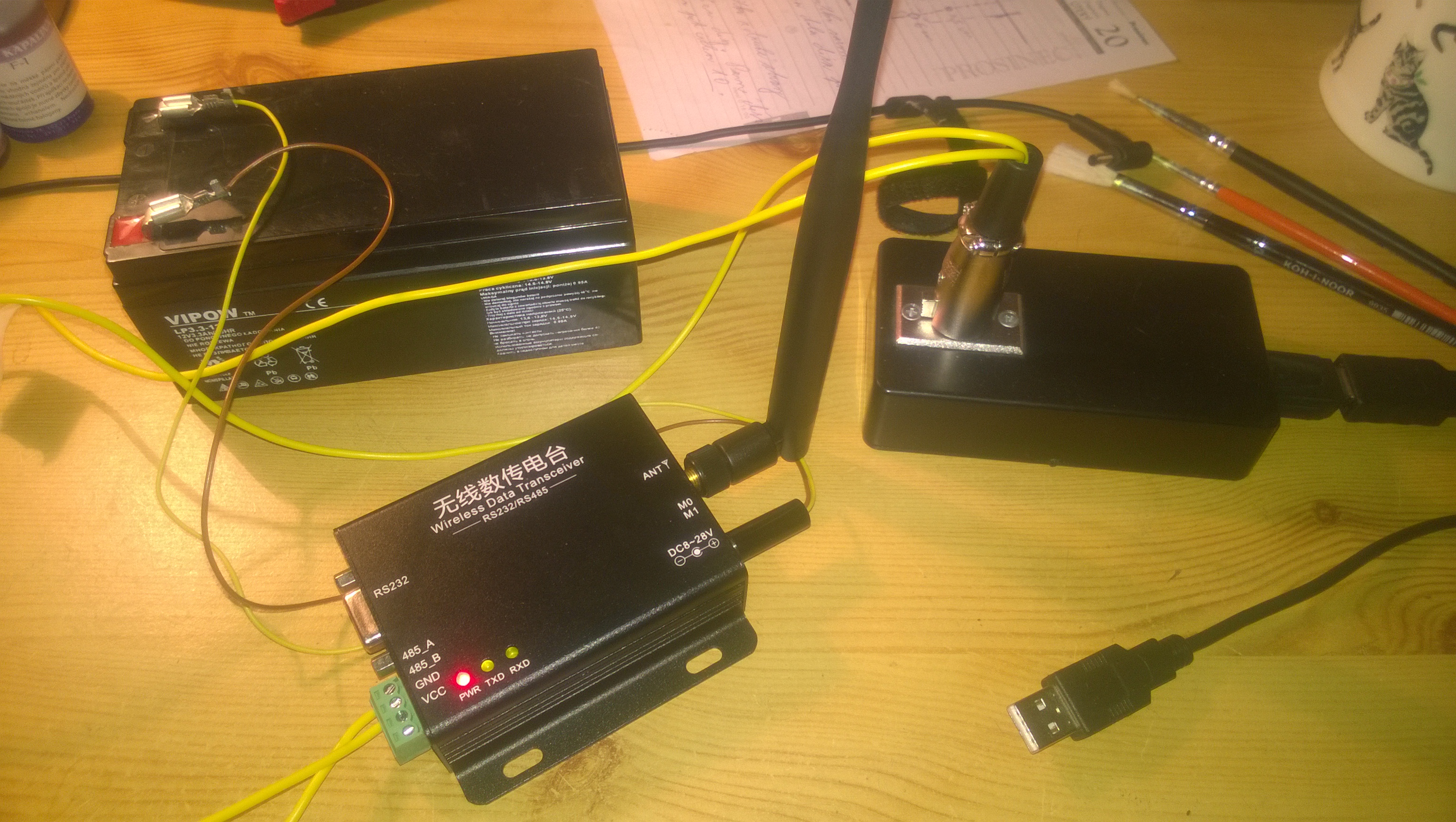
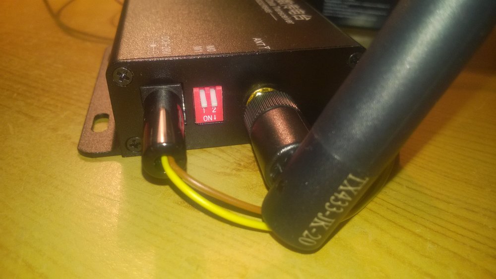
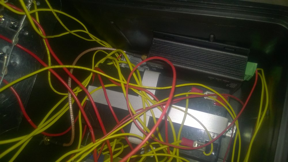
The result of testing the E62-DTU-100 This is a module that is capable of doing point to point transfer! So if you need to connect a PC with 1 module or other modules to connect the cable, it is the ideal module. Multiple devices must have a different module. I try it in time. If someone wanted the E62 I have several unpacked pieces. Buy for a purchase. Please write to a private message. -
forumowy projekt opensource systemu pirotechnicznego
Royal924 odpowiedział(a) na zk1959 temat w Forumowy system pirotechniczny
Now I'm getting tested for the E62-DTU-100 wireless module. You can not recommend it for now. An error occurred. When using multiple modules it is unreliable. I've tried the default settings and I also tried setting recommended by ZK1959 (Set to COM: 9600, 8N1; and on RF: 19200, transparent.) when setting 19200 knk does not work. I can provide the datasheet. link to test video: https://uloz.to/!L7H5BLcsYDlS/knk1302-mp4
-
forumowy projekt opensource systemu pirotechnicznego
Royal924 odpowiedział(a) na zk1959 temat w Forumowy system pirotechniczny
do you know how to create a test diode? (instead of an electric pill) -
forumowy projekt opensource systemu pirotechnicznego
Royal924 odpowiedział(a) na zk1959 temat w Forumowy system pirotechniczny
Yes, it would be fantastic to have feedback: yes modules 1,2,3 are connected -
forumowy projekt opensource systemu pirotechnicznego
Royal924 odpowiedział(a) na zk1959 temat w Forumowy system pirotechniczny
Hello, I have good news for all who are want a wifi module. I tried the E62-DTU-100. So far, everything works. I'll do a few more tests and write a review. -
forumowy projekt opensource systemu pirotechnicznego
Royal924 odpowiedział(a) na zk1959 temat w Forumowy system pirotechniczny
Hello, have you got anyone plan the KNK1302 in the program to make it drilled? -
forumowy projekt opensource systemu pirotechnicznego
Royal924 odpowiedział(a) na zk1959 temat w Forumowy system pirotechniczny
Zajęło to trochę czasu, zanim zaprogramować ATmega, teraz wszystko działa. Dziękuję za radę -
forumowy projekt opensource systemu pirotechnicznego
Royal924 odpowiedział(a) na zk1959 temat w Forumowy system pirotechniczny
Ok, sorry, I did not understand this. The voltageis now ok. The board is still not working. ATmega16 will start to warm up quickly. Maybe it is burned and I have only programmed one AT that was shorted in the first pcb. ok, przepraszam, ja nie rozumiem tego. Napięcie jest prawidłowe. Płyta nadal nie działa. AT ATmega16 zaczyna szybko ogrzać. Może to spalony i mam zaprogramowany tylko jeden w tym zwarcie w pierwszej płytce. -
forumowy projekt opensource systemu pirotechnicznego
Royal924 odpowiedział(a) na zk1959 temat w Forumowy system pirotechniczny
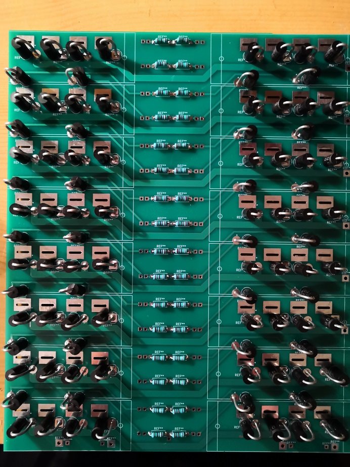
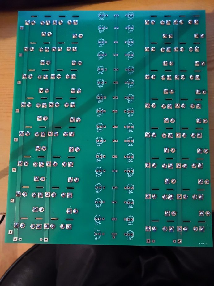
The instruction is written (point 16) that the resistance resistor 4K7 should be 5V. But I measured 0. The photo is 4K7 marked 0. Podręcznik jest napisany (pkt 16), w tym rezystor 4k7 być 5V. Ale mierzy 0. Zdjęcie jest oznaczony 4K7 0-ty -
forumowy projekt opensource systemu pirotechnicznego
Royal924 odpowiedział(a) na zk1959 temat w Forumowy system pirotechniczny
przetwornicę is ok I build third board and problém is the same! I really do not know where the error is. Three pcbs are not working. I have measured the voltage in some pcb sections (viz pict. 2) https://s3.postimg.org/c1ohaezjn/WP_20170709_004.jpg https://s21.postimg.org/a13nag7lj/Inked_WP_20170709_001_LI.jpg -
forumowy projekt opensource systemu pirotechnicznego
Royal924 odpowiedział(a) na zk1959 temat w Forumowy system pirotechniczny
Akumulator is ok According to the manual, the diode 1N5822 should be below 12V. może przetwornicy DC jest zły Zgodnie z instrukcją by 1N5822 dioda powinna być niższa niż 12V. -
forumowy projekt opensource systemu pirotechnicznego
Royal924 odpowiedział(a) na zk1959 temat w Forumowy system pirotechniczny
I made a new pcb (knk1302) board, at diode 5822 the voltage is 0.01V and the resistor resistor 10K 0V. If I take the fuse (2A) on the diode is 10V and on the 4.5V resistors. I do not know where the mistake can be. Zrobiłem nową płytę PCB, sprawdzić napięcie 0,01V dioda 5822 oraz rezystoru o oporze 10K 0V. Jeśli usunąłeś bezpiecznik (2A) na diodzie jest 10V i 4.5V rezystoru rozumie gdzie błąd może być. -
forumowy projekt opensource systemu pirotechnicznego
Royal924 odpowiedział(a) na zk1959 temat w Forumowy system pirotechniczny
Avula good work! wszystko" zwarte I meaning electric shock Some pictures of my book, corrected PCB in the last Picture https://postimg.org/image/4iza2jdcx/ https://postimg.org/image/incwcpqd5/ https://postimg.org/image/4rw6bj4cb/